ZITHA SPECIALTYSPECIALTY FIBER CABLES Technical Inquiry

Red fiber optic patch cord test diagram

A red fiber optic patch cord can be tested using a light source and power meter setup to measure insertion loss, return loss, and verify polarity.Conceptual Test Diagram

[Light Source (Tx)] --- [Test Jumper] --- [Patch Cord Under Test (Red)] --- [Test Jumper] --- [Power Meter (Rx)] Components Explained

  • Light Source (Tx): Provides a stable optical signal at the required wavelength (e.g., 850 nm for multimode, 1310/1550 nm for singlemode) ( ).
  • Test Jumper: A short, verified fiber patch cord used to connect the light source to the patch cord under test without disturbing the reference measurement ( ).
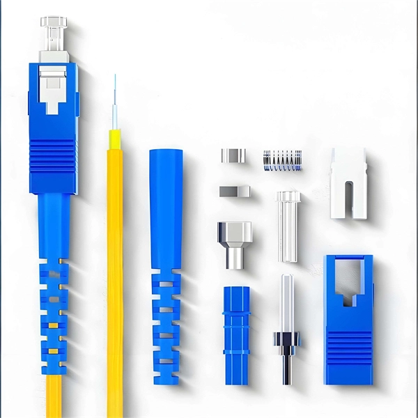
  • Patch Cord Under Test (Red): The fiber optic patch cord being evaluated for performance.
  • Power Meter (Rx): Measures the optical power received to calculate insertion loss (IL) and return loss (RL) ( ).
Testing Steps
  1. Polarity Verification: Ensure the transmitting end (Tx) of the patch cord aligns with the receiving end (Rx) of the network device. For duplex or multi-fiber cords, follow standard polarity schemes to prevent misalignment ( ).
  2. Insertion Loss (IL) Measurement: Connect the light source to one end of the patch cord and the power meter to the other. Record the power loss in dB to ensure it meets specifications ( ).
  3. Return Loss (RL) Measurement: Measure the reflected signal back to the source to ensure minimal reflection, typically using an optical loss test set (OLTS) or power meter with RL capability ( ).
  4. Endface Inspection: Use a fiber microscope or 3D interferometer to check for scratches, contamination, or defects on the connector endfaces ( ).
  5. 3D Interferometric Testing (Optional): For high-precision applications, measure connector geometry parameters such as curvature radius, apex offset, and fiber height ( ).
Notes
  • Always verify that test jumpers are within specification before testing the patch cord to avoid invalid results ( ).
  • Red patch cords are often used to indicate a specific wavelength or network type; ensure labeling matches network documentation.
  • Testing should follow industry standards such as ISO/IEC, TIA/EIA, or manufacturer specifications to certify the patch cord for deployment ( ). This setup ensures that the red fiber optic patch cord is tested for signal integrity, minimal loss, correct polarity, and connector quality, providing reliable performance in optical networks.
Red fiber optic patch cord test diagram

How to Test Patch Cords and Fiber Jumpers

Channel Testing vs Permanent Link TestingCopper Patch Cord Quality TestsFiber Jumper Quality TestsDo Your Own Patch Cord and Fiber Jumper TestingIn addition to performing channel testing after equipment cords are in place to determine problems with patch cords and jumpers, they can also be tested individually—and its good practice to test a sampling of cords, especially if you''re purchasing them from a different supplier than the rest of your cabling plant. Fluke Network''s DSX Series PatchSee more on flukenetworks

Videos of Red Fiber optic patch Cord test Diagram

more videos

Watch video0:42Fiber Patch Cord Quality Inspection with Customer – Endface, IL/RL & 3D Interferometer Testing Wirenet Telecom Technology Co,Ltd;753 views2 weeks agoWatch video0:15How to test E2000 patch cord with 400X fiber optic microscope #ftth #patchcord #microscope Wirenet Telecom Technology Co,Ltd;4.6K views4 months agoWatch video0:44How to perform through-light inspection of completed production patch cords? Neofibo Technology25.7K viewsMar 11, 2024Watch full videoCorningTranslate this result

Fiber Optic System Testing Tutorial - Corning

Patch cords or equipment jumpers are used to bridge the network electronic ports to the fiber optic link contained between patch

Related Video Reference

This video was associated with the source search result. Verify technical details against current product documentation and project requirements.

Technical note

This reference is intended for preliminary specialty-cable research. Compatibility, link budgets, fire performance, installation methods, test limits and applicable standards must be verified for the specific project.

Still Have a Technical Question?

Use the inquiry form to describe a specialty cable route, fire requirement or testing question.

Start an Inquiry